Temperature Range |
Max. Temp. To Which Tube Can Be Exposed |
Tube Specifications |
Approx. Throttling Range Min.–Max. |
Approx. Temperature Change Per Turn Of Adjusting Screw |
Standard Position Of Bushing Or Union On Tube (If Required) |
* Standard Thermowell available If Required |
Code Number |
||||||||
Fahrenheit (°F) |
Centigrade (°C) |
Active Length (H) |
Inactive Length (J) |
Overall Length (A) |
Diameter (B) |
Material |
°F |
°C |
°F |
°C |
Drawing |
Immersion Length* |
|||
Smallest Throttling Ranges – Smallest Adjustable Ranges |
|||||||||||||||
-50 – 200 |
0 – 90 |
300° F |
17” |
4 ¾” |
21 ¾” |
¾” |
Stn. Stl. |
4-12 |
2 - 6 |
28 |
16 |
18” |
A-709 |
U = 17” |
320b |
120 – 300 |
50-150 |
4-12 |
2 –7 |
30 |
17 |
322a |
|||||||||
Medium Throttling Ranges – Medium Adjustable Ranges |
|||||||||||||||
60 – 300 |
20 - 150 |
300°F |
13” |
4 ¾” |
17 ¾” |
¾ “ |
Stn. Stl. |
5-15 |
3-8 |
40 |
22 |
14” |
A-709 |
U = 13” |
331a |
220 – 450 |
100 – 230 |
700°F |
13” |
4 ¾” |
17 ¾” |
¾ “ |
Stn. Stl. |
5-15 |
3-8 |
38 |
21 |
14” |
A-709 |
U = 13” |
332b |
355 – 575 |
180 – 300 |
700°F |
13” |
4 ¾” |
17 ¾” |
¾ “ |
Stn. Stl. |
5-15 |
3-8 |
37 |
20 |
14” |
A-709 |
U = 13” |
333b |
485 – 700 |
250 – 370 |
700°F |
13” |
4 ¾” |
17 ¾” |
¾ “ |
Stn. Stl. |
5-15 |
3-8 |
36 |
20 |
14” |
A-709 |
U = 13” |
334 |
645 – 850 |
340 – 455 |
1400°F |
13” |
4 ¾” |
17 ¾” |
¾ “ |
Stn. Stl. |
5-15 |
3-8 |
35 |
19 |
14” |
A-709 |
U = 13” |
335 |
800 - 1000 |
430 – 540 |
1400°F |
13” |
4 ¾” |
17 ¾” |
¾ “ |
Stn. Stl. |
5-15 |
3-8 |
34 |
19 |
14” |
A-709 |
U = 13” |
336 |
950 - 1150 |
510 – 620 |
1400°F |
13” |
6 ¾” |
19 ¾” |
¾ “ |
Stn. Stl. |
5-15 |
3-8 |
33 |
18 |
14” |
A-709 |
U = 13” |
337 |
1100-1300 |
590 – 700 |
1400°F |
13” |
6 ¾” |
19 ¾” |
¾ “ |
Stn. Stl. |
5-15 |
3-8 |
33 |
18 |
14” |
A-709 |
U = 13” |
338 |
1200 - 1400 |
650 - 760 |
1400°F |
13” |
6 ¾” |
19 ¾” |
¾ “ |
Stn. Stl. |
5-15 |
3-8 |
33 |
18 |
14” |
A-709 |
U = 13” |
339 |
Widest Throttling Ranges – Widest Adjustable Ranges |
|||||||||||||||
35 – 300 |
0 – 150 |
300° F |
8 ½ “ |
5 ½ “ |
14 “ |
¾ “ |
Stn. Stl. |
7-22 |
4-12 |
62 |
34 |
9 ½ “ |
A-709 |
U = 8 ½ “ |
341a |
150 – 500 |
65 – 260 |
700° F |
8 ½ “ |
5 ½ “ |
14 “ |
¾ “ |
Stn. Stl. |
7-22 |
4-12 |
50 |
33 |
9 ½ “ |
A-709 |
U = 8 ½ “ |
342 |
370 –700 |
180 – 370 |
700° F |
8 ½ “ |
5 ½ “ |
14 “ |
¾ “ |
Stn. Stl. |
7-22 |
4-12 |
55 |
30 |
9 ½ “ |
A-709 |
U = 8 ½ “ |
343 |
580 – 900 |
300 – 480 |
1400° F |
8 ½ “ |
5 ½ “ |
14 “ |
¾ “ |
Stn. Stl. |
7-22 |
4-12 |
53 |
29 |
9 ½ “ |
A-709 |
U = 8 ½ “ |
344 |
790 – 1100 |
420 – 590 |
1400° F |
8 ½ “ |
5 ½ “ |
14 “ |
¾ “ |
Stn. Stl. |
7-22 |
4-12 |
52 |
29 |
9 ½ “ |
A-709 |
U = 8 ½ “ |
345 |
950 – 1200 |
510 – 680 |
1400° F |
8 ½ “ |
7 ¼ “ |
15 ¾ “ |
¾ “ |
Stn. Stl. |
7-22 |
4-12 |
51 |
28 |
9 ½ “ |
A-709 |
U = 8 ½ “ |
346a |
1100 – 1400 |
590 – 760 |
1400° F |
8 ½ “ |
7 ¼ “ |
15 ¾ “ |
¾ “ |
Stn. Stl. |
7-22 |
4-12 |
50 |
28 |
9 ½ “ |
A-709 |
U = 8 ½ “ |
347a |
1300 – 1600 |
700 – 870 |
2000° F |
8 ½ “ |
9 ¼“ |
17 ¾ “ |
** ¾ “ |
Inconel |
8-24 |
4-13 |
52 |
29 |
9 ½ “ |
None |
None |
348a |
1500 - 1800 |
815 - 985 |
2000° F |
8 ½ “ |
9 ¼ “ |
17 ¾ “ |
** ¾ “ |
Inconel |
8-24 |
4-13 |
52 |
29 |
9 ½ “ |
None |
None |
348a |
*To be used only where full immersion length,
“U”, will be exposed to the heat.
**Also
available in .840” diameter, heavier wall.
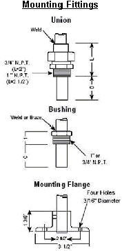
The fittings shown to the left are
optional and must be specified if desired. It
is essential that the exact active length of the tube is exposed to the heat source. If the bushing or union in the standard
position will not permit this, order with a shorter or longer “C” or
“D” dimension. See the Table above. Also specify size, ¾” or 1” NPT. A ¾” NPT
is required for wells; a 1” NPT is required on .840” diameter tubes. The flange is fastened with a set screw.

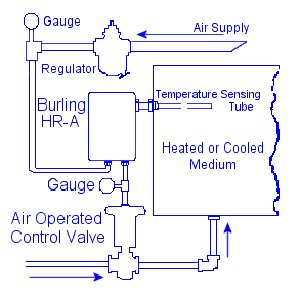
 Typical Installation
*Ordering Information
1.
Model
and Code Number
2.
Temperature
Range, ºF or ºC
3. Max. or Min. Temperature
on Tube
4. Modifications or
Fittings, if any.


